Skip to content
Geometric Dimensioning and Tolerancing (GD&T) or Geometrical Tolerancing and Dimensioning (GT&D) is a pictorial language employed in engineering drawings to state the tolerance of variation in the geometry of a part. It guarantees assembly fit and functionality of parts even in the case of slight variations in production.
If you’re a designer, machinist, or quality inspector, then it is essential to know What is GD&T and How is it Used? So that the product is repeatedly applied with equal quality and functionality.
This blog post will elaborate on the use of these tolerances. In the modern high-precision production era, using the GD&T is imperative in getting clear, precise design ideas across effectively. It decorates confusion, enhances communication between manufacturers and designers, and makes parts interchangeable. So, read till the end.
Significance of GD&T in Contemporary Manufacturing
As opposed to conventional tolerancing, which only regulates the dimensions and location of features, GD&T permits regulation of form, orientation, location, and runout. It offers an accurate model that resembles reality in the manufacturing processes and the functions of the parts.
GD&T vs Traditional Tolerancing
| Feature | GD&T | Traditional Tolerancing |
| Controls | Geometry, size, form | Size and location only |
| Communication | Symbolic and universal | Varies by interpretation |
| Flexibility | High | Low |
| Function-based design | Yes | Limited |
| Inspection clarity | High | Moderate |
By using GD&T, manufacturers minimize scrap they have better quality, and it is easier to communicate with global teams.
GD&T Basics for Beginners
GD&T basics for beginners start with understanding the core elements:
- Datums: The hypothetical points by which measures are determined.
- Features: Real aspects of a constituent (holes, surfaces).
- Feature Control Frames (FCFs): Boxes with the symbols of geometric tolerancing.
FCFs are essential to the application of GD&T. They provide details of how a feature is to behave concerning the datum(s) and how much variations are permitted.
GD&T Feature Control Frame Explained
A Feature Control Frame normally contains:
- The geometric aspect mark (e.g., flat, location)
- The tolerance value
- The datum references (where available)
Common GD&T Tolerance Types
Some of the common GD&T tolerance types used across industries include:
| Straightness | Flatness | Circularity | Cylindricity |
| Concentricity | Perpendicularity | Parallelism | Angular Tolerance |
| Position | Profile of a Line / Surface | Runout | |
Each symbol is identified with a certain meaning and application in the specification of behavioral aspects of part geometry during manufacturing and post-processing.
Benefits of Using GD&T in Manufacturing

The benefits of GD&T are many compared with conventional dimensioning systems. That is why it is popular in aerospace, automotive, defense, and precision engineering:
- Better Communication: Standardized language where the designs are devoid of ambiguity.
- Cost Effectiveness: Both stricter controls where there is a necessity and less strict tolerances where there is an opportunity to save costs.
- Improved Quality Control: An ordered inspection with specific datums and quantifiable features.
- Increased Coverage: Helps parts that have minor variations to satisfy their designed requirements.
- International Compatibility: The international standards ( ASME Y14.5, ISO 1101 ) promote international manufacturing cooperation.
Teams equipped with a thorough grasp of what GD&T is and how it is employed will be able to streamline processes and reduce risks at both production and QA levels.
How to Read GD&T on Drawings
Learning how to read GD&T on drawings is crucial for anyone involved in product design, machining, or quality inspection. The following tips are good:
- First, the Datums: Voyage with the reference frame.
- Interpret Feature Control Frames: decode symbols; decode tolerances.
- Take a look at the Material Condition Modifiers: Knowledge of MMC (Maximum Material Condition), LMC, or RFS.
- Use Drawing hierarchy: Reconsider notes, section views, and general tolerances.
It is mainly about training and practice. Most practitioners complete official courses in certified GD&T or consult the ASME Y14.5 standard.
Practical use of GD&T
Due to its high-precision nature, GD&T is widely preferred in the high-precision sectors. The following are some examples:
Aerospace:
Making sure that turbine blades are aligned and engine parts are correct.
Automotive:
Ensuring in-mass production part fit.
Medical Devices:
Requirements of close tolerances of manufactured implants and surgical instruments.
Robotics:
The exact match between mechanical and electric components.
A report by MarketsandMarkets shows that the total global CAD market that employs GD&T tools heavily is projected to reach a total of 13.8 billion in 2028, through a significant increment by 2023 that is pegged at 9.3 billion, indicative of the growing dependence on tolerancing precision and digital manufacturing.
What is the Role of GD&T in the Industry?
GD&T is applied throughout the design the inspection of the typical workflow:
- Design: The engineers use the concept of geometric controls that are defined using functions.
- Manufacturing: GD&T is used as a language by machinists to decode tolerances and to make setups of equipment.
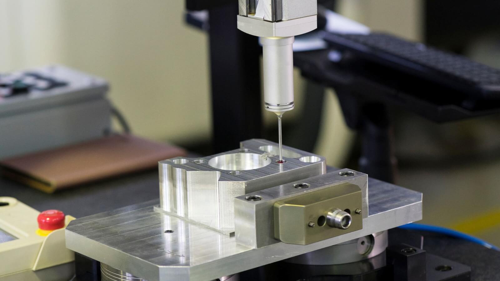
- Inspection: QA employs the use of CMMs (Coordinate Measuring Machines) to check the correctness of parts against GD&T standards.
This is a closed circuit that guarantees quality from blueprint to the end product.
Conclusion
Knowing what is GD&T and how is it used? can help you greatly improve your design, production, and quality control abilities. It ensures lower error levels, greater functionality, and ensures your parts match the engineering requirements accurately and repeatably.
By learning to interpret GD&T feature control frames, recognizing GD&T symbols and meanings, and grasping the benefits of using GD&T in manufacturing, you’re taking a major step toward becoming a proficient modern engineer or technician.
Want to make GD&T work? Begin by looking over your drawings and deciding how the geometric tolerancing is meeting the design intent.
FAQs About What is GD&T and How is it Used?
Q1. What is GD&T?
A: Geometrical Dimensioning and Tolerancing, called GD&T, is a symbolic tolerance checking language used to specify tolerances on technical drawings.
Q2. Is GD&T required in manufacturing?
A: No, however, it is essential when handling complex parts and assembly whereby the role as well as inter-switchability is of great importance.
Q3. Which are the most prevalent GD&T symbols?
A: Position, flatness, perpendicularity, and profile are some of the most common GD&T tolerance types used.
Q4. Would it be possible to apply GD&T to 2D base drawings exclusively?
A: A regular use of GD&T can be found in any commonly used 2D drawing, but they also excel well in 3D model-based definitions (MBD).
Q5. Where should I begin learning GD&T?
A: Begin with understanding the GD&T basics for beginners and progress through certified training programs or online tutorials.