Skip to content
When it comes to producing impossible angles, intricate curves, or multi-dimensional surfaces, how do manufacturers achieve such perfection? This is where the true magic of Creating Complex Geometries with CNC Machining transforms challenging designs into reality with unmatched accuracy and control.
In the highly specialized world of Creating Complex Geometries with CNC Machining, being the best means mastering precision, complexity, and efficiency factors that truly set components apart. At the forefront of this technological revolution is CNC machining itself. Nevertheless, intricate designs with CNC Machining play a critical role in producing advanced components like aerospace turbine blades, biomedical implants, and high-performance automotive parts. These designs go beyond just using powerful tools; they require smart design strategies, cutting-edge CAD/CAM software, and precise process control.
Mastering such complexity ensures not only functionality but also the highest level of performance and durability in demanding applications. This blog post will cover all these perspectives. So, it’s time to get into the precision world of complex geometry CNC machining. So, let’s begin.
Why Complex Geometries Matter More Than Ever
Modern industries are shifting from mass production to customization, light weighting, and performance-based design. This trend demands intricate geometries that enhance function while reducing material waste. The main reasons include:
- Internal cooling channel-based thermal management of aerospace components that enhances flight efficiency
- It is also the kind of prosthetic implants that are made within the predisposition backbone of a patient as a way of improving integration and comfort.
- Optimized lattice pattern heat exchangers that optimize for minimum space designs that dissipate heat
Creating Complex Geometries with CNC Machining is essential for producing parts like aerospace turbine blades, biomedical implants, and high-performance auto components. These intricate designs are nearly impossible with traditional methods. As industries push for greater efficiency and precision, CNC machining is key to overcoming modern geometry challenges.
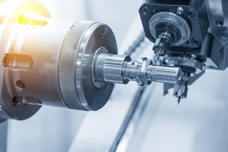
Explore the Hidden Secrets of 5-Axis CNC Machining
5-axis CNC machines are considered to be one of the best machining solutions. Unlike 3-axis or even 4-axis machines, 5-axis CNC systems can simultaneously move the cutting tool or the part along five different axes. This flexibility empowers engineers to cut virtually any shape with unprecedented control. The Top Benefits:
Multi Angle Machining
Reach difficult to mill undercuts, compound angles, and sidewalls easily without having to rotate. The functionality saves time preparing the setup process, augments efficiency, and limits the use of humans.
Improved Tolerances
Fewer setups, more precision. Essential to industries such as the aerospace industry, in which microns may become a factor.
Surface Quality
This parameter enables the best possible tool contact along curved surfaces in the meat and leisure industries that frequently require post-processing, to enhance the finishing in Washington.
Time efficiency
The reduced lead time and tool changeover lead to quick cycle time, which reduces the cost of production.
Improved Tool Life
You can get out of the bad position of the tool, so that the tool is not the reason why it wears or breaks down. This gives rise to more regular results and reduced tooling expenses.
Real-World Application
In Formula One, ultra-lightweight suspension arms with hollow interiors are crafted using Creating Complex Geometries with CNC Machining, specifically through 5-axis CNC processes. These high-performance parts must endure extreme stress at high speeds while maintaining aerodynamic efficiency, something only achievable through precise, multi-axis machining.
Top Five Best CNC Machining Design Tips
Regardless of the capability of CNC equipment, a bad design may result in over-cutting and tool breakage, a bad finish, or even a failure. On the other hand, smart design is needed in CNC parts that are complex. However, the machining process.
The best design suggestions for using complex geometries start here:
- Prioritize Manufacturability
Always consult your machinist during the design phase. What looks good in CAD might not be practical for a machine. Early feedback ensures fewer revisions and cost-effective production.
- Avoid Deep Cavities
Long tools can bend or vibrate, leading to poor finishes or breakage, especially at high speeds or with hard materials. Design with shallow, accessible features where possible.
- Use Generous Radii
Sharp internal corners require small tools that slow down machining. Larger radii allow stronger tools, faster cuts, and better surface finishes.
- Reduce Skinny Walls
Thin walls can flex, vibrate, or break. Reinforce them with fillets or design in layers to maintain strength during machining.
- Balance Aesthetics and Function
Smooth, sculpted designs may look great, but aren’t always practical. If aesthetics are essential, use alternative finishing methods that don’t compromise machinability.
Choose the Best Multi-Toolpath Strategies for 3D Surfaces.
The secret to mastering complex 3D surfaces lies in how you program the toolpaths. Advanced CNC software offers a variety of strategies tailored to different part shapes and surface types.
Most Common Multi-Toolpath Techniques:
- Z-Level Finishing (Waterline Cuts): This approach really works well when you want steep walls and regular step-downs going vertically. It generates low levels of scalloping, and it is common in applications done on turbine blades and molds.
- Spiral Toolpaths / Morph Toolpaths: these guarantee a continuous motion, or less tool wear and better surface finish. They work well on freeform surfaces such as impellers or ergonomic grips.
- Scallop Machining: keeps the scallop height constant to have uniform finishing. It is used where the consistency of a surface is important over contoured surfaces.
- The Projection Toolpaths: They work using the projected curve on a 3D surface, which can be applied on surfaces that are not flat, e.g., the logo or surface etching.
Top result for Combine Strategies
In many cases, the combination of methods can work best. As an example, roughing may involve a 3D offset toolpath to remove bulk material fast, followed by a spiral finishing toolpath used to finish with precision. Adaptive clearing can be employed to enhance chip evacuation in complicated pockets in some situations.
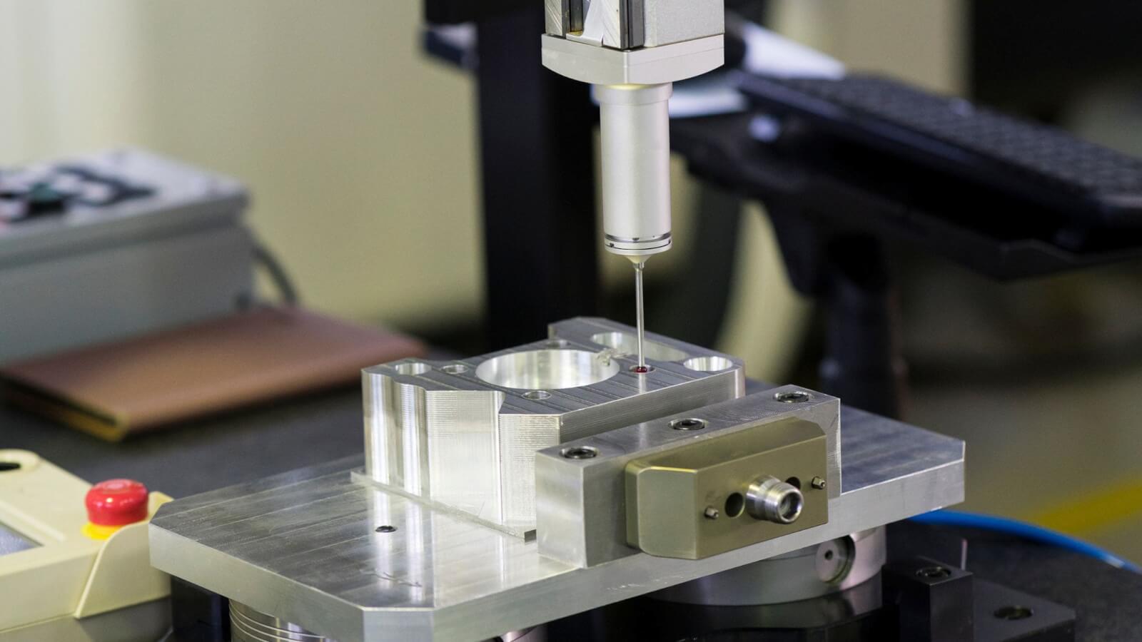
Toolpath Simulation Is Key
Never fail to take the tool path test in your CAM system. This prevents collisions, verifies tool accessibility, and verifies the quality of the surface. It can also be used to guess the cycle time, allow predicting tool wear, and confirm that the chosen strategy will produce the desired surface finish.
One of the Siemens NX case studies demonstrated that integration of the spiral and Z-level toolpaths increased the uniformity of the surface finish on aerospace blades by 25 percent, with more than 30% reduction in time spent on post-processing.
CAD/CAM Software for Complex Shapes
Complex geometry machining wouldn’t be possible without powerful CAD/CAM platforms that support multi-axis, parametric, and generative design workflows. The right software bridges the gap between concept and production.
Best-in-Class Tools:
- Siemens NX: High-end CAM of turbine blades and mold tools with simulation, multi-axis machining, and digital twin capabilities.
- Autodesk Fusion 360: Low costs but robust with integrated CAE/CAD/CAM tools; perfect in case of startups and small producers.
- MasterCAM: An Industry standard that has good multi-axis support, many tool libraries, and is very compatible with machines.
- HyperMill: Referred to as being precise when working on 5-axis tools, particularly with the aerospace and medical industries.
- SolidCAM: Incorporation with SolidWorks is seamless, efficient, and real-time simulation is enabled.
Features to Look For: Creating Complex Geometries with CNC Machining
- 5-axis simultaneous tool path to generate maximum control
- Real-time collision avoidance and detection
- Mapping of the surface curvature in optimized path planning
- Time-saving automated roughing & finishing stratagems
- Specific CNC Machine-specific post-processor customization
A plug-in CAD/CAM is non-negotiable; it is the key to machining precise and complex components that are characteristic of today’s engineering world.
Service we provide: Ceramic CNC Machining
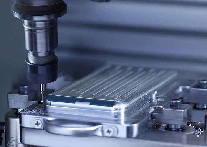
Surface Finish Control on Curved Components
The quality of your surface finish doesn’t just impact aesthetics—it affects functionality, performance, and durability. For complex parts, surface finish control is both a science and an art.
Factors Influencing Surface Finish:
- Tool Selection: Wherever smoother, rounded curves are on the surface, select ball-end mills or bullnose tools. You can use coated tools to enhance wear resistance.
- Feed Rate & RPM: The finer finishes are obtained with lower feeds and high RPMs. But the balance is the key to preventing overheating and wearing of the tools.
- Step-over Distance: Short step-overs produce closer scallops and finishes are uniform better however will take a longer time.
- Coolant Flow: Proper coolant flow cools and minimizes friction and temperature to increase finish and tool life.
- Toolpath Overlap: There must be strategic overlap of paths to avoid marks, particularly in transition areas.
Finishing Passes
Add a separate finishing pass with tighter tolerance settings and reduced tool load. This step alone can cut polishing time by 50%, especially on polished aluminum, titanium, or mold-grade steels.
Surface Roughness Targets:
- Ra 1.6 μm: Standard for general industrial parts
- Ra 0.8 μm: Common for aerospace and automotive applications
- Ra 0.2 μm or better: Required for optical components, medical implants, or sealing surfaces
Use surface profilometers to measure results, and adjust your finishing parameters accordingly for optimal output.
Final Thoughts
Making the Impossible Possible
The era of flat planes and square holes is over. Engineers today must design parts that are stronger, lighter, and more functional, which means embracing complexity in creating complex geometries
But complexity without strategy is chaos. The real advantage lies in understanding how to:
- Harness the 5-axis CNC machining benefits
- Implement design tips for intricate part features
- Optimize multi-toolpath strategies for 3D surfaces
- Choose the best CAD/CAM software for complex shapes
- Maintain flawless surface finish control on curved components
With the right mix of design insight, machine capability, and software intelligence, you can push the limits of what CNC machining can achieve. Are you ready to take your designs from concept to complex reality? Do follow us and feel free to give us your feedback.
FAQs
Can 5-axis machining create undercuts and compound curves?
A: Yes. 5-axis machines can approach the part from virtually any angle, allowing access to undercuts and sculpted curves that would be impossible on traditional 3-axis systems.
What industries benefit most from complex geometry CNC machining?
A: Aerospace, automotive, medical, defense, and energy industries benefit the most due to high-performance part requirements.
What’s the typical cost impact of machining complex geometries?
A: While upfront programming and machining costs are higher, they are often offset by better performance, reduced weight, and fewer assemblies.
How do I choose the right toolpath strategy?
A: Consider part geometry, surface finish requirements, and machining time. Use simulation tools in CAM software to evaluate.
Is additive manufacturing better for complex shapes?
A: For internal geometries and lattice structures, yes. However, CNC machining still delivers superior mechanical strength and surface finish for many external features.